|
Expansion of Hong Kong International Airport into a Three-Runway System |
|
|
|
Contents |
Tables
|
Table 2.1:__ Arrangements for Cases of Enhanced Silt Curtain_ 4 Table 2.2:__ Silt Curtain Arrangements for Marine Works / WSRs 5
|
Figures
1
Introduction
|
1.1
Background
Under the Environmental Impact Assessment Ordinance, the Environmental Impact Assessment (EIA) Report (Register No.: AEIAR-185/2014) prepared for the “Expansion of Hong Kong International Airport into a Three-Runway System” (the project) has been approved by the Environmental Protection Department (EPD), and an Environmental Permit (Permit No.: EP-489/2014) has been issued for the project. Pursuant to Condition 2.15 of the Environmental Permit (EP), the Airport Authority Hong Kong (AAHK) shall prepare a Silt Curtain Deployment Plan covering marine works involving silt curtain deployment for the project.
Mott MacDonald Hong Kong Limited (MMHK) was appointed by AAHK as the Environmental Team (ET) and one of the tasks of the ET is to establish a Silt Curtain Deployment Plan (SCDP) with associated pilot test on silt curtain efficiency for the relevant marine works of the project.
1.2
Project
Description
This project covers the expansion of the existing airport into a three-runway system (3RS) with key project components comprising land formation of about 650 ha with ground improvement and all associated facilities and infrastructure including taxiways, aprons, aircraft stands, a passenger concourse, an expanded Terminal 2, all related airside and landside works, associated ancillary and supporting facilities, diversion of aviation fuel pipelines and diversion of submarine 11kV cables.
1.3
Purpose & Scope
As specified in Condition 2.15 of the EP:
“The Permit Holder shall, no later than 3 months before the commencement of marine works involving deployment of silt curtains of the Project, deposit 3 hard copies and 1 electronic copy of a silt curtain deployment plan (The Plan) with the Director. The Plan shall include at least the following information/specifications:
(i) the construction programme and details on the design, operation and maintenance of silt curtain(s) to be deployed during the construction;
(ii) a pilot test on the efficiency of the silt curtain system shall be conducted during the early stage of construction to confirm the silt curtain removal efficiency; and
(iii) the pilot test shall be conducted during the highest current speed condition, covering both flood and ebb tides, and include measurement of current speed and direction, turbidity and suspended solids.”
This SCDP has been prepared in accordance with the EP requirements and details the requirements for implementation of silt curtains during the 3RS Project construction phase, which shall be adopted by all relevant Contractors under the 3RS Project. The key items covered by this Plan include:
§ Summary of marine works and sensitive receivers requiring deployment of silt curtains;
§ Key components and design specifications for floating and cage-type silt curtains;
§ Requirements for installation, operation, maintenance and removal / re-deployment of the silt curtains during construction; and
§ Methodology for the pilot test on silt curtain efficiency (to be implemented by the ET).
The SCDP was first submitted to EPD in July 2016. This is an updated version of the SCDP taking into account the latest design development and construction details.
1.4
Report Structure
Following this introductory section, this SCDP is structured as follows:
Section 2 Marine Works Requiring Deployment of Silt Curtains
Section 3 Silt Curtain Design Specifications
Section 4 Silt Curtain Deployment
Section 5 Pilot Test on Silt Curtain Efficiency
2.1
General
In accordance with the recommendations of the approved EIA report, the following marine works activities / plants require deployment of silt curtains during construction phase:
§ Sand blanket laying activities (‘Type III’ silt curtains required in a double layer arrangement primarily around the active eastern works areas and configured to minimise suspended solids release during ebb tides);
§ Marine filling activities (‘Type II’ or ‘Type III’ silt curtains required in a double layer arrangement primarily around the eastern and south-western openings between partially completed seawalls and configured to minimise suspended solids release during ebb tides);
§ Field joint excavation for the submarine cable diversion (silt curtains surrounding the grab dredger);
§ Modification of existing seawall e.g. demolition of existing northern seawall as part of 3RS land formation and temporary removal of existing seawall for connection of the submarine cables to the airport island (silt curtains to completely enclose the seawall modification activities); and
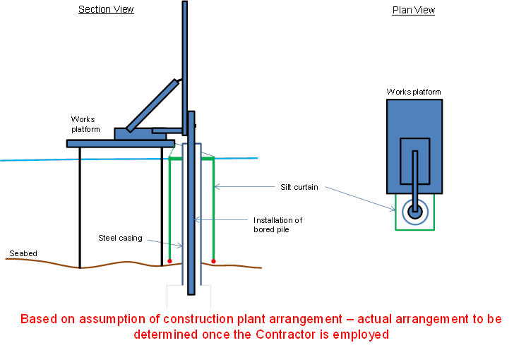
§ Piling activities for construction of new runway approach lights and Hong Kong International Airport Approach Area (HKIAAA) marker beacons (silt curtains to completely enclose the piling works).
‘Type II’ and ‘Type III’ silt curtains refer to the United States Army Corporation of Engineers (USACE) classification system which describes silt curtains according to the prevailing hydrodynamic and metocean conditions that they are suitable for. In general, Type II silt curtains are designed to suit sites with a small to moderate current of up to about 1 m/s, and where wind and wave action can be present but are not considered a major force. Type III silt curtains are designed for sites with higher energy environments, with currents in excess of 1.5 m/s, and can be deployed in a tidal region and be subject to wind and wave action. Specific components of ‘Type II’ and ‘Type III’ silt curtains are shown in Figure 3.1 and Figure 3.2.
Aside from the silt curtains to be deployed around construction activities, the following water sensitive receiver (WSR) also requires silt curtains / silt screens to be deployed around the sensitive receiver location:
§ WSR C7a (Cooling water intake at Hong Kong International Airport (North)) – requires double layer silt curtains at the intake points; and
§ WSR C7a and C8 (Future Hong Kong-Zhuhai-Macao Bridge Hong Kong Boundary Crossing Facilities (HKBCF) Intake) – requires silt screens at the intake points.
2.2
Latest Design Status
2.2.1
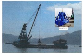
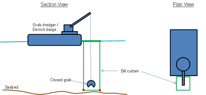
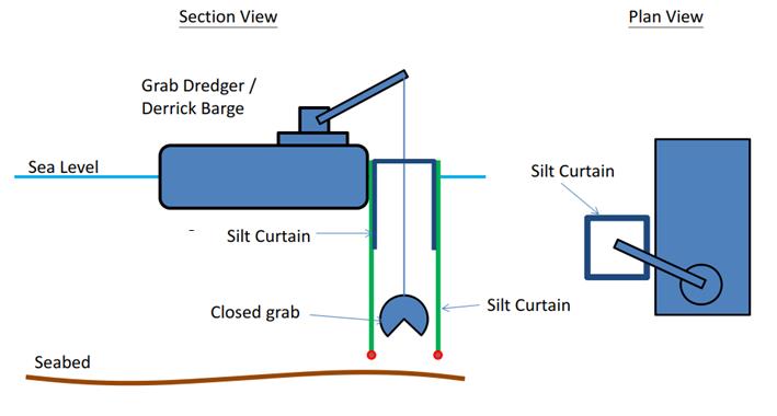
Activities Requiring Silt Curtains
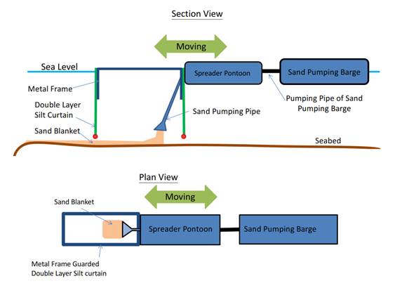
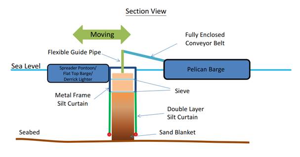
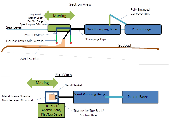
Based on the construction details available at the time of preparation of this Plan, the methods for sand blanket laying would include closed grab methods, hydraulic pumping with spreader pontoon, and other methods. Where such closed grab methods are adopted, the proposed silt curtain would be a full enclosure cage-type surrounding the grab (such full enclosures are typically associated with a higher silt removal efficiency). Where hydraulic pumping with spreader pontoon is adopted, a cage-type metal frame with overhanging double-layer silt curtain surrounding the sand blanket laying activity would be implemented. Compared to the open configuration silt curtains proposed in the approved EIA report (which have gaps required for marine vessel access), adoption of these full enclosure-type silt curtains surrounding the source of the suspended solids (SS) release during sand blanket laying activities would more effectively contain SS release and prevent sediment plumes from spreading. As a result, the proposed full enclosure-type silt curtain is expected to be able to better contain the SS release than the original arrangement.
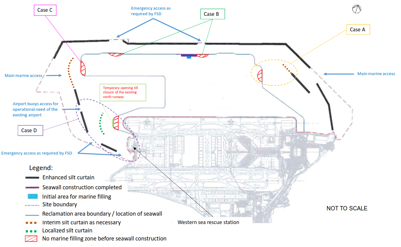
For marine filling activities, instead of primarily around the eastern and south-western openings between partially completed seawalls, an enhanced silt curtain will be deployed for a wider protection of the reclamation area. The indicative enhanced silt curtain arrangement before commencement of marine filling activities is provided in Figure B.1 (a) of Appendix B. Prior to commencement of marine filling activities, an advance seawall of at least 200m will be provided in accordance with Condition 2.26 (ii) of EP. During different period of the marine filling activities, the location of seawalls (partially completed seawalls with rock core to high tide mark and filter layer on the inner side) together with the enhanced silt curtain would be arranged to contain the SS generated from marine filling activities within the reclamation area so as to minimise SS release outside the project site boundary. At some locations, openings at the enhanced silt curtain for marine access, emergency access and operational need of the existing airport have to be provided along the enhanced silt curtain. Details are listed in Table 2.1 and shown in Figure B.1(a) of Appendix B. The ET and IEC will conduct regular inspections particularly for the arrangement of Case D during marine filling activities. Further, the water quality monitoring under the Environmental Monitoring and Audit (EM&A) mechanism will be followed according to the Updated EM&A Manual to safeguard the surrounding water quality.
Table 2.1: Arrangements for Cases of Enhanced Silt Curtain
|
Case |
Location |
Reasons for Provision of Opening |
Arrangements to Be Adopted |
|
A |
At the eastern side of project site area |
To enable efficient evacuation of all marine vessels during adverse weather / typhoon / emergency within a short period of time. |
· Arrangement Option (1): No marine filling activities (except filling activities for construction of seawall) will be undertaken within the no marine filling zone as indicated in Figure B.1(a) for Case A if there is no seawall to the immediate west of the opening; or · Arrangement Option (2): An interim silt curtain should be added to the north of inner enhanced silt curtain if marine filling activities are undertaken within no marine filling zone before seawall construction. |
|
B |
At the northern side of project site area |
Two openings are required by Fire Services Department (FSD) as emergency access for their sea rescue boats to the works area. |
· No marine filling activities (except filling activities for construction of seawall) will be undertaken within the no marine filling zone as indicated in Figure B.1(a) for Case B if there is no seawall to the immediate south of the opening. |
|
C |
At the western side of project site area |
To enable efficient evacuation of all marine vessels during adverse weather / typhoon / emergency within a short period of time. |
· Arrangement Option (1): No marine filling activities (except filling activities for construction of seawall) will be undertaken within the no marine filling zone as indicated in Figure B.1(a) for Case C if there is no seawall to the immediate east of the opening; or · Arrangement Option (2): An interim silt curtain should be added to the west of the future runway if marine filling activities are undertaken within no marine filling zone before seawall construction. |
|
D |
At the southwestern of project site boundary |
An access for operational need of the existing airport is required for maintenance of the airport buoys. Two openings are required by FSD as emergency access for their sea rescue boats from Western Sea Rescue Station to the works area. |
· No marine filling activities (except filling activities for construction of seawall) will be undertaken within the no marine filling zone as shown in Figure B.1(a) for Case D if there is no seawall to the immediate east of the openings. |
|
· Arrangement at a later stage: At a later stage, the three separate sections of enhanced silt curtain located to the west of the reclamation area will be removed. A localised silt curtain should be provided to the west of the existing north runway if marine filling activities are undertaken to the west of the existing north runway when there is a temporary opening at the seawall (see Case D as shown in Figure B.1(a)). |
Upon commencement of the marine filling activities with advance seawall and enhanced silt curtain surrounding the reclamation area, the remaining sand blanket laying activities would be protected by the seawall and the enhanced silt curtain. The enhanced silt curtain arrangement would provide wider protection of the reclamation area (rather than the localised protection of specific works areas only), hence would enable better capture and retention of SS generated by the marine construction activities. Once this enhanced silt curtain is in place, all sand blanket laying activities as well as marine filling activities would be protected, hence the localised full-enclosure-type silt curtains surrounding the sand blanket laying activities would only be required before this enhanced silt curtain is installed.
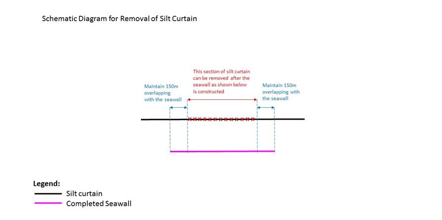
At a later stage, when seawalls are completed for a certain section, enhanced silt curtain will be phase out. The Contractor is required to maintain an overlapping length of at least 150m for seawall and enhanced silt curtain as shown in Figure B.1(b) of Appendix B.
Illustrations of the tentative layouts and configurations for the silt curtains associated with key marine construction activities is shown in Appendix B.
A summary of the latest silt curtain requirements for different construction activities / locations is shown in Table 2.2. It should be noted that these are subject to further detailed design and implementation.
Table 2.2: Silt Curtain Arrangements for Marine Works / WSRs
|
Relevant Marine Works / WSRs |
Silt Curtain Type Proposed |
Configuration Requirement |
Deploying Location |
|
Sand blanket laying activities (before commencement of marine filling activities) |
|
|
|
|
Hydraulic pumping with spreader pontoon |
Contractor’s Customised Cage Type Silt Curtain |
Full enclosure (See Appendix B.2) |
Surrounding the sand blanket laying activity |
|
Closed grab methods |
Cage Type Silt Curtain |
Full enclosure (See Appendix B.3) |
Surrounding the grab |
|
Other methods |
Contractor’s Customised Cage Type Silt Curtain |
Full enclosure (See Appendices B.4 to B.6) |
Surrounding the sand blanket laying activity |
|
After commencement of marine filling activities (including remaining sand blanket laying activities and removal of existing northern seawall) |
‘Type II’ Floating Silt Curtain (for areas with maximum current speed < 1m/s) ‘Type III’ Floating Silt Curtain (for areas with maximum current speed > 1m/s) |
Open / Double layer (See Appendix B.1) |
Various locations surrounding the reclamation area |
|
Field joint excavation for the submarine cable diversion |
Cage Type or Floating Silt Curtain |
Full enclosure (See Appendix B.3) |
Surrounding the grab |
|
Modification of existing seawall (excluding the northern seawall) |
Floating Silt Curtain |
Full enclosure (where practicable) (See Appendix B.7) |
Surrounding the seawall modification activity |
|
Piling activities for construction of new runway approach lights and HKIAAA marker beacons |
Cage Type or Floating Silt Curtain |
Full enclosure (See Appendix B.8) |
Surrounding the piling activity |
|
WSR C7a |
Floating Silt Curtain |
Full enclosure (See Appendix B.9) |
Surrounding the intake location |
2.2.2
WSRs Requiring Silt Screens
According to the approved EIA report, WSRs C7a and C8 would require silt screens to be installed prior to commencement of marine construction works.
For C8, as specified in the Updated EM&A Manual, allowable SS levels at these intakes are dependent on the operational tolerance of individual intakes, and should be separately proposed by the ET and agreed with the Independent Environmental Checker (IEC) and respective operators of the intakes prior to commencement of construction activities or commencement of operation of the seawater intake (whichever is later). As this intake is not yet operational, the tolerance for SS is subject to further liaison with the project proponent of HKBCF. Similarly, the need for, and installation of silt screens at this intake is subject to agreement with the project proponent of HKBCF.
It should be noted that the exceedances of SS predicted by the approved EIA report is based on the criteria of SS not exceeding 30% above ambient levels. Given that the allowable SS levels at these intakes are to be determined by the operational tolerance of individual intakes and agreement with respective operators (as stated in the Updated EM&A Manual), the need for silt screens at C8 would be further reviewed once the design tolerance of the intakes at C8 are available.
For C7a, silt screens were proposed in addition to silt curtains in order to achieve an 84% total SS reduction (from 12.15 mg/l to 1.94 mg/l). However, as per the requirements of the Updated EM&A Manual, the operational tolerance levels of the intakes has been agreed with the operator of C7a, whereby the SS levels at the intakes may reach up to 52 mg/l without adversely affecting operation of these intakes[1]. Under this updated criterion, there would be no adverse impact at C7a due to the predicted SS elevations associated with the 3RS Project, hence silt screens at the intake points are unlikely to be necessary. It should also be noted that the intakes of C7a would be relocated as part of the 3RS Project during construction phase, hence it would not be cost effective to install silt screens at C7a. Silt curtains surrounding the intakes of C7a are proposed and would be retained as a precautionary measure. Due to the progress of reclamation works and the future diversion of C7a, the silt curtain arrangements surrounding the intakes would be periodically revised subject to Contractor’s arrangements. In case of high SS levels measured at C7a during impact water quality monitoring, the need for, and design of silt screens at C7a may be further reviewed during construction phase.
2.3
Construction Programme
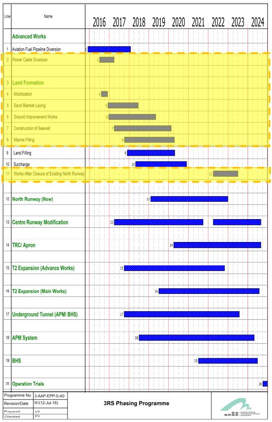
The construction programme for relevant marine works at the time of preparation of this Plan is presented in Appendix A. Given the scale and complexity of the project and the fact that a number of key project components are still subject to detailed design prior to implementation, please refer to another EP submission namely Construction Works Schedule and Location Plans for the latest version of construction programme.
3.1
Types of Silt Curtains to be Deployed
As specified in Table 2.2, the following types of silt curtains will be adopted for different works areas / locations:
§ Floating Silt Curtains
§ Cage Type Silt Curtains
The following sub-sections outline the technical requirements for these different silt curtain types.
3.2
General Requirements
3.2.1
Manufacturer / Supplier
Silt curtains components (including all individual parts and accessories) shall be procured from reputable manufacturers / suppliers with a proven track record (at least 10 years) on manufacture / supply of such components. The manufacturer / supplier shall be quality certified (i.e. ISO 9001 or equivalent) and its products shall have appropriate certification of quality / conformance to the manufacturer’s specifications.
All silt curtains procured shall have relevant project references / records of field tests demonstrating their applicability for deployment in open sea marine environments and conditions comparable to those in Hong Kong waters.
For each construction contract requiring deployment of silt curtains for the Project, the Contractor shall submit details of the manufacturer / supplier’s specifications, certifications and references to the AAHK, ET and the IEC for review and comment at least 4 weeks before commencement of silt curtain deployment activities. Any changes to these manufacturer / supplier’s details during construction phase would require resubmission to AAHK, ET and IEC prior to implementation.
3.3
Requirements for Floating Silt Curtains
3.3.1
Major Components
All floating silt curtains shall comprise at least the following components:
§ Geotextile fabric
§ Flotation
§ Ballast chain
§ Seams and Joints
§ Anchors
§ Warning lights / marker buoys
Additional requirements on the silt curtain structure apply to ‘Type II’ and ‘Type III’ specifications, which are covered in Sections 3.3.3 to 3.3.4.
3.3.1.1 Silt Curtain Fabric
For silt curtains, the fabric material shall comprise a geotextile such as woven polypropylene or reinforced polyvinyl chloride (PVC) membrane. Impermeable fabrics are not recommended due to the excessive pressure that would be induced on the curtain due to tidal conditions, hence the fabric shall have a suitably low permeability that allows water to pass through under pressure, but will retain suspended solids. The fabric including seams and connecting parts shall have adequate tensile strength to withstand the pressures induced by the wind, wave and sea current conditions at the location to be deployed.
3.3.1.2 Floatation
The floatation device shall comprise flexible and buoyant units contained within a floatation sleeve or collar that is attached to the silt curtain. The buoyancy of the floatation units shall be adequate to support the full weight of the curtain including the pressure weight induced by tidal currents acting on the silt curtain surface. A freeboard of at least 10cm shall be maintained above the water surface at all times.
3.3.1.3 Ballast Chain
The ballast chain (or load lines) shall comprise a steel chain that is incorporated into the bottom hem of the silt curtain. The chain shall be sufficiently weighted to hold the curtain in a vertical position. Connecting devices from the load lines to connecting joints of the silt curtain shall be able to develop the full breaking strength of the chain.
3.3.1.4 Seams and Joints
Seams of the silt curtain fabric shall be heat sealed and shall develop the full strength of the fabric. Jointing devices such as ropes, chains and shackles shall be made of materials with adequate strength and shall not limit the full strength of the silt curtain fabric.
3.3.1.5 Anchors
Anchors shall comprise either dig type (e.g. stakes, grappling hook, plow or fluke-type) or weight type (e.g. concrete blocks) with adequate hold / weight to retain the silt curtain in the same position relative to the seabed without interfering with the action of the silt curtain. Lateral anchors (one on either side of the silt curtain) shall be attached to a floating anchor buoy via an anchor line, which connects to the top of the silt curtain. Anchor spacing should be between 15 to 30 m apart. For areas with faster current velocity, closer spacing shall be adopted as necessary to stabilise the silt curtain.
3.3.1.6 Warning Lights / Marker Buoys
To warn other marine vessels not to approach or run into the silt curtains, yellow marker buoys fitted with yellow flashing lights shall be used to indicate the position of the anchors and silt curtain system. The buoys and lights shall be located on both sides of the silt curtain at regular intervals (no more than 60m apart) along the entire length of silt curtain.
3.3.2
Silt Curtain Depth
The depth (vertical length from the water’s surface to the bottom) of the silt curtain shall be sized to the water depth at the location of deployment. The base of the silt curtain skirt shall be anchored to within 30cm of the seabed even during high tides, hence adequate depth of silt curtain shall be allowed in the total silt curtain depth to cater for tidal changes. Given that the tidal range at the Project area can reach >2m, the base of the silt curtain may be affected by deposition of sediment during low tides. Design of the silt curtain shall take into account the potential additional drag pressure on the silt curtain due to sediment deposition at low tide. To ease pressure on the silt curtain, the bottom 1 to 2m of silt curtain material may be made of more permeable fabric to enable better flow-through of water at the base of the curtain.
3.3.3
Additional Requirements for ‘Type II’ Floating Silt Curtains
In addition to the major components specified in Section 3.3.1, ‘Type II’ floating silt curtains adopted for the Project shall be based on the specifications shown in Figure 3.1.
|
|
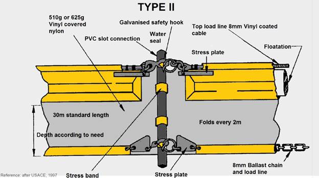
Additional requirements for ‘Type II’ silt curtains include:
§ Load lines comprising steel cables fabricated into the top of the silt curtain fabric with a breaking strength in excess of 5,000 kg.
§ Stress plates / stress bands provided along silt curtain joints as needed to strengthen the links between silt curtain panels.
§ Base anchors (in addition to lateral anchors) shall be deployed and shall be attached via an anchor line to connectors at the bottom of the silt curtain (not directly to the silt curtain fabric) with sufficient slack to allow for tidal changes.
3.3.4
Additional Requirements for ‘Type III’ Floating Silt
Curtains
In addition to the major components specified in Section 3.3.1, ‘Type III’ floating silt curtains adopted for the Project shall be based on the specifications shown in Figure 3.2.
|
|

Additional requirements for ‘Type III’ silt curtains include:
§ Load lines comprising steel cables fabricated into the top of the silt curtain fabric with a breaking strength in excess of 5,000 kg.
§ High density reinforced geotextile fabric to form the silt curtain panels.
§ Additional mid-section load line / cable and associated connectors.
§ Stress plates / stress bands provided along silt curtain joints as needed to strengthen the links between silt curtain panels.
§ Base anchors (in addition to lateral anchors) shall be deployed and shall be attached via an anchor line to connectors at the bottom of the silt curtain (not directly to the silt curtain fabric) with sufficient slack to allow for tidal changes.
§ Lateral anchor lines shall contain enough slack to allow the buoy and curtain to float freely with tidal changes without pulling the buoy or curtain down.
3.4
Requirements for Cage Type Silt Curtains
Cage type silt curtains shall mainly comprise the geotextile fabric with ballast chain / weight, a metal frame and associated connectors to affix the silt curtain to the frame. The frame shall be made of non-corrosive metal and properly designed to achieve structural integrity of the silt curtain.
The geotextile fabric shall be mounted and/or affixed to all four sides of the frame using seamed joints with sufficient overlap to prevent leakage of suspended solids. The silt curtain shall contain a roll up mechanism to enable the geotextile fabric to be rolled up when not in use. The design of the mechanism must enable the geotextile fabric to remain attached to the sides of the frame during roll up and roll down (i.e. prevent billowing of the fabric away from the cage frame).
Both the length of the frame and the geotextile fabric shall be measured and cut to fit the water depths at the location of deployment. The exact length shall be flexible to cater for changes in tidal level.
3.5
Onsite Field Trial of Silt Curtain System
An onsite field trial of the new silt curtain system should be conducted by the Contractor prior to commencement of marine works. This is separate from the pilot test to be conducted by the ET as specified in the EP Clause 2.15 and Section 5 of this document. This onsite field trial to be conducted by the Contractor is recommended for silt curtain systems that have been specifically designed and customised for this Project, and for any standard market-available systems which do not have adequate project references that are comparable to the hydrodynamic conditions of Hong Kong. To date, a number of customised cage type silt curtain designs have been proposed by Contractors. Details are shown in Appendix B.2 to B.6.
The purpose of the field trial is primarily to test the physical strength properties of the silt curtain system as a whole and its ability to withstand the marine conditions at the works area. The findings of the trial will inform whether any modifications to the silt curtain or supplementary components are required to improve its durability and resistance to daily tidal and current conditions, which will help to safeguard the Contractor’s works programme and avoid excessive maintenance / repair works.
For the field trial, the Contractor should deploy the silt curtain system at a representative location of the works area. The trial silt curtains should comprise at least three panels of silt curtain with at least two connecting joints and all associated components (anchors, ballast chain, marker buoys, etc.), to enable the silt curtain system as a whole to be tested. The silt curtain system should remain deployed for at least 24 hours before being recovered and checked for weak spots and damage. The findings of the field trial and the recommendations for silt curtain system improvement, if any, shall be submitted to the AAHK, ET and IEC for review.
4.1
Layout and
Positioning
Floating silt curtains required for the land formation works of the Project will need to be adjusted regularly to fit with construction works schedule / progress. Exact positioning of these silt curtains will depend on Contractor’s arrangements, however the following requirements shall be followed:
§ Silt curtains shall be deployed for the marine works activities / plants specified in Section 2.1. An initial bathymetry survey should be conducted to determine the required depth of silt curtains.
§ Silt curtain layout shall be configured to minimise SS release during ebb tides.
§ Where necessary to maintain access for construction vessels, a semi-open configuration with overlapping silt curtains at the access points shall be adopted. Gaps between overlapping silt curtains shall be approx. 100 m wide (or as wide as necessary to enable marine vessel access) with an overlapping length of at least 150 m except the cases as described in Section 2.2.1.
§ As far as possible, silt curtains shall not be placed perpendicular to the dominant tidal / current direction but should be angled to deflect flows away from the marine works areas being protected
§ Where double floating silt curtains are deployed, the parallel distance between the silt curtains shall not exceed 2x the perpendicular distance between the silt curtain panels and the lateral anchor / marker buoys.
§ All silt curtains shall be located entirely within the boundary of the temporary works area of the 3RS Project (refer to the EP submission of Construction Works Schedule and Location Plans for the boundary of the temporary works area, which can be accessed from http://env.threerunwaysystem.com/en/ep-submissions.html)
Based on best available information at the time of preparation of this Plan, illustrations of the tentative layouts and configurations for the silt curtains associated with key marine construction activities as well as the customised silt curtain designs proposed by Contractors are shown in Appendix B. These tentative layouts and arrangements are subject to further changes once the relevant designs are finalised by the Contractors.
Throughout the construction period for marine filling activities if there are any changes on the arrangement of enhanced silt curtain as shown in Figure B.1(a), the Contractor is required to submit updated enhanced silt curtain plans showing the layout of the enhanced silt curtain, location of seawall and marine filling areas which fulfil the design principle in Section 2.2.1 for agreement with AAHK, ET and IEC. A checklist of the implementation schedule of the enhanced silt curtain is provided in Appendix C. The latest layout of enhanced silt curtain plan should be submitted to EPD for record.
For all construction activities requiring deployment of silt curtains, the Contractor shall propose their specific silt curtain design and layout arrangements (covering the full duration and all phases of their respective marine works including any re-positioning / re-deployment of silt curtains) at least 4 weeks prior to commencement of construction for agreement with AAHK, ET and IEC. Any subsequent changes to the silt curtain design and layout would require resubmission to AAHK, ET and IEC prior to implementation.
4.2
Silt Curtain Installation
Silt curtains shall be installed completely before commencement of any marine works requiring silt curtains as presented in Table 2.2. Prior to installation of silt curtains, the Contractor shall undertake a thorough check for defects and/or damages particularly in the silt curtain fabric, at the seams, and at the jointing / connector locations. Any defects and/or damages shall be rectified before commencing installation. Requirements for marine mammal watching during installation shall refer to the Marine Mammal Watching Plan, which can be accessed from http://env.threerunwaysystem.com/en/ep-submissions.html.
4.2.1
Floating Silt Curtains
The furled floating silt curtains shall be launched into the sea by derrick / crane boats and floated into position. Anchors shall be carefully lowered to the seabed at the specified intervals. Care shall be taken to ensure that lateral anchor points are in the correct positions prior to attaching the anchor lines / anchor buoy to the silt curtain. After attaching the silt curtain to the anchors and before unfurling the silt curtains, a check shall be conducted on the ‘lay’ of the curtain to confirm the positioning and slack allowances are correct. Where necessary, final adjustments should be made to the anchors, before the furling lines are released to allow the silt curtain skirt to drop. Where base anchors are also required, connection of the anchor lines to the silt curtain shall be done by divers after unfurling the silt curtain.
4.2.2
Cage Type Silt Curtains
The assembled cage frame shall be securely attached to the section of the construction vessel involved in the marine works (e.g. around the grab of the grab dredger or the marine piling area). The rolled up silt curtains attached to the cage frame should be lowered to seabed level after the frame position has been fixed and the vessel is in the correct location for the marine works.
4.2.3
Record of Installation
For both floating and cage type silt curtains, an initial diver inspection of the installed silt curtain shall be carried out prior to commencement of marine works, to check that the silt curtain has been properly installed with no gaps / tears in the curtain fabric. Underwater photographic records shall be taken after each installation to demonstrate proper deployment of the silt curtain system. A summary of the initial diver inspection records including photographic records shall be included in the Contractor’s monthly environmental reports, which shall be submitted to AAHK and the ET within three days from the end of the reporting month. The full diver inspection report shall be made available to the ET and IEC upon request.
4.3
Operation of Silt Curtains
4.3.1
Silt Curtain Inspections
During operation of the silt curtains, inspections shall be carried out by the Contractor to check that the silt curtains are not damaged and are performing as intended. Requirements for marine mammal watching during operation shall refer to the Marine Mammal Watching Plan, which can be accessed from http://env.threerunwaysystem.com/en/ep-submissions.html.
Visual inspections of the silt curtain condition and function shall be carried out daily along the length of silt curtains deployed. During visual inspections, the observer shall check that the silt curtains are maintained in the correct positions with no obvious defects / entanglement, the marker buoys and lights are present and operational, and there is no observable muddy water passing through the silt curtain system. Any floating refuse trapped by the silt curtain shall be removed as part of the visual inspection.
In addition, diver inspections for conducting more thorough underwater inspections shall be carried out by the Contractor fortnightly and whenever there is suspected sediment release due to ineffectiveness of silt curtains (e.g. from the results of environmental monitoring of suspended solids by the ET). Diver inspections shall cover at least a 10 m length of silt curtain or one whole silt curtain panel (whichever is greater) at each diving location, and at intervals of at least every 200 m along the length of silt curtains deployed. The diver inspections shall check that the silt curtain fabric is intact, the silt curtain depths and anchor positions are correct, and there is no damage / breakage in anchor and load lines. Photographic records shall be taken during each underwater inspection. All identified defects / damage shall be photographed and the position recorded on GPS to enable the affected areas to be subsequently located for in-situ repair where appropriate.
Weekly and ad hoc site inspections carried out by the ET and fortnightly site inspections carried out by the IEC shall include visual checks on the silt curtain locations and effectiveness. Where the silt curtains deployed are identified by the ET and/or IEC to be ineffective or inadequate for controlling sediment release, the Contractor shall make appropriate adjustments or provide additional silt curtains as necessary to improve and meet the water quality requirements of the Project.
4.3.2
Procedures for Adverse Weather Conditions
During adverse weather conditions (e.g. typhoon signal No.3 or higher), no marine works shall be conducted and potentially affected silt curtains shall be retracted where possible to avoid unnecessary damage. The divers / crew responsible for maintenance of the silt curtains shall be on standby as soon as typhoon signal No.1 is raised, and silt curtains shall not be retracted until the marine works are fully halted. The Contractor is responsible for coordinating the construction workers and the silt curtain maintenance divers / crew to enable sufficient time for any works involving retraction of silt curtains before typhoon signal No.3 is raised.
After typhoon signal No.3 is lowered, retracted silt curtains shall be re-deployed and visual inspection shall be carried out to confirm the integrity of the silt curtain prior to re-initiation of marine works. If any damage is observed or suspected, divers shall be deployed for further inspection and affected silt curtains shall be repaired or replaced before relevant marine works are re-initiated.
4.3.3
Record of Inspections
Visual inspections of the silt curtains carried out by the Contractor on a daily basis (Section 4.3.1 refers) shall be recorded on the inspection checklist. Example inspection checklists are presented in Appendix D. All checklists shall be signed by the Contractor and kept on board the responsible maintenance / construction vessel and made available to the ET and IEC upon request for checking and auditing purpose. A summary of the records of the fortnightly diver inspections including photographic records shall be included in the Contractor’s monthly environmental reports, which shall be submitted to AAHK and the ET within three days from the end of the reporting month.
For re-deployment of silt curtains after adverse weather, initial diver inspections shall be conducted for all re-deployed silt curtains prior to re-commencement of affected marine works. Underwater photographic records shall be taken after each re-installation to demonstrate proper deployment of the silt curtain system. A summary of the initial diver inspection records for all re-deployed silt curtains due to adverse weather including photographic records shall be included in the Contractor’s monthly environmental reports, which shall be submitted to AAHK and the ET within three days from the end of the reporting month. The full diver inspection report shall be made available to the ET and IEC upon request.
4.4
Maintenance of Silt Curtains
4.4.1
Equipment
The Contractor shall keep an inventory of silt curtain parts / tools and maintain adequate supplies and spare parts onboard the relevant maintenance / construction vessels at all times. Spare silt curtain sheets (at least 20 m for each continuous length of silt curtains deployed) shall be pre-fabricated and available on site to enable easy installation in the event of emergency replacement. A team of trained divers / crew shall be available at all times during construction to attend to any unforeseen incidences involving the silt curtains.
4.4.2
Maintenance / Repair
Any damage or faults identified in the silt curtain system shall be repaired by the Contractor immediately. Where the damage / fault is minor, the Contractor may undertake in-situ maintenance and repair by qualified divers without the need for retracting the silt curtains. Where such in-situ maintenance and repair is conducted, the Contractor shall ensure that another diver is on standby, the appropriate warning flags / signals are in place, and the captain or foreman of the maintenance / construction vessel has communication channels open and ready to promptly alert other vessels to avoid the affected silt curtain area during the maintenance and repair.
Where the damage / fault is extensive or cannot be easily repaired in-situ, the Contactor shall demobilise and retrieve the affected silt curtain and replace to new ones. The procedures shall follow that for removal / re-deployment as specified in Section 4.5.
4.4.3
Record of Maintenance and Repairs
Where diver inspections and/or in-situ maintenance and repair has been carried out, the diver shall prepare the diver inspection report and record the observations and subsequent actions taken to maintain / repair the silt curtains, including photographic records. A summary of the diver inspection records including photographic records and any rectification actions taken shall be included in the Contractor’s monthly environmental reports, which shall be submitted to AAHK and the ET within three days from the end of the reporting month. The full diver inspection report shall be made available to the ET and IEC upon request.
4.5
Silt Curtain Removal / Re-deployment
Prior to removal of silt curtains, all marine works for which the silt curtains are deployed shall be stopped and visual inspection of the water quality within the area protected by silt curtains shall be conducted to confirm no sediment plume remaining within the works area before commencing silt curtain removal.
4.5.1
Floating Silt Curtains
Floating silt curtains shall be removed by detaching the chain connecting the silt curtain to the anchors, before rolling up and lifting the silt curtains and marker buoys / lights onto derrick / crane boats. Care should be taken to protect the silt curtain skirt from damage as it is dragged from the water. The remaining anchors shall be individually connected to the crane by divers and carefully lifted off the seabed for recovery onto the boats to minimise disturbance to the seabed. Re-installation shall follow the procedures specified in Section 4.2.1.
For re-positioning / re-deployment, the marine works for which the silt curtains are deployed shall be temporarily ceased and visual inspection of the water quality within the area protected by silt curtains shall be conducted to confirm no sediment plume remaining within the works area before commencing silt curtain re-deployment. Alternatively, marine works may continue provided that the original silt curtains remain in place while the new silt curtains are installed, and only after the new silt curtains are fully deployed and checked as functioning properly shall the original silt curtains be removed. Requirements for marine mammal watching during re-positioning / re-deployment shall refer to the Marine Mammal Watching Plan, which can be accessed from http://env.threerunwaysystem.com/en/ep-submissions.html.
4.5.2
Cage Type Silt Curtains
For cage type silt curtains, the silt curtains shall be rolled up and either securely wrapped to the top of the frame or detached from the frame completely before the cage frame is lifted and removed or re-positioned as required. Re-installation where required, shall follow the procedures specified in Section 4.2.2.
4.5.3
Record of Re-deployment
Initial diver inspections shall be conducted for all re-deployed silt curtains (floating and cage-type) prior to commencement of affected marine works. Underwater photographic records shall be taken after each re-installation to demonstrate proper deployment of the silt curtain system. A summary of the initial diver inspection records for all re-deployed silt curtains including photographic records shall be included in the Contractor’s monthly environmental reports, which shall be submitted to AAHK and the ET within three days from the end of the reporting month. The full diver inspection report shall be made available to the ET and IEC upon request.
5.1
General
As specified in EP Clause 2.15(ii) and (iii), a pilot test on silt curtain system shall be conducted during the early stage of construction to confirm the silt curtain removal efficiency, and this pilot test shall be conducted during the highest current speed condition, covering both flood and ebb tides, and include measurement of current speed and direction, turbidity and suspended solids.
This section describes the proposed methodology for conducting a pilot test on silt curtain efficiency.
5.2
Purpose and Scope of Pilot Test
The purpose of the pilot test is to determine and confirm the silt removal efficiency of the double layer floating type silt curtains proposed for the 3RS Project with comparison to the relevant assumptions of the EIA Report.
The objective is to apply the pilot test results with an aim to optimize the installation, workmanship and operation of the silt curtains to achieve effectiveness. The Contractor is required to deploy and improve silt curtains following the recommendations of the ET and achieve the efficiency to the satisfaction of ET and IEC.
It should be noted that other types of silt curtains, e.g. cage-type silt curtain, is only deployed for small and localised works areas, hence is not the primary concern in relation to SS release due to Project activities and should not be the focus of this pilot test.
Regardless of the measured efficiency of the silt curtain system, the event and action plan as part of the EM&A requirements of the Project should only be based on the monitoring results at the designated stationary monitoring stations as specified in the Updated EM&A Manual.
5.3
Timing and Duration
The pilot test will be conducted once and will be scheduled to take place during the highest current speed conditions. The exact dates are subject to commencement and arrangement of sand blanket laying / marine filling activities for the land formation and will be notified to EPD before commencement of the pilot test.
The pilot test is proposed to be conducted over a period of one week, with one sampling day for obtaining baseline conditions beforehand and subsequently three sampling days for silt curtain efficiency testing. Measurements shall be taken four times (twice during flood tide and twice during ebb tide) each day, with the interval between consecutive samples no less than one hour. The total number of samples per tide per day is thus:
2 replicates x 3 depths x 6 stations x 2 monitoring events = 72 samples per tide per day
Prior to the pilot test, a diver survey shall be undertaken by the Contractor to check and confirm the silt curtain is in good condition.
During the silt curtain efficiency testing, sand blanket laying or marine filling activities shall be actively conducted within the works areas protected by the silt curtains to be tested, and shall be operating at close to but not exceeding the maximum productivity (to be determined based on Contractor’s information). The sand blanket laying or marine filling activities shall be located as close to the silt curtain boundary as practicable.
During the whole pilot test, the surrounding environment should be controlled as far as practicable such that there would be no other major SS-generating construction activity operating concurrently, or marine vessel movements in the near vicinity.
5.4
Monitoring Locations
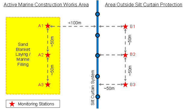
Monitoring stations will be set up on both sides of the silt curtain to be tested (representing conditions both inside the marine works area behind the silt curtain and conditions outside of the silt curtain protected area). The arrangements for the monitoring stations are as follows:
|
Inside Marine Works Area |
Three monitoring stations spaced about 50 m apart and located within the active sand blanket laying / marine filling activities area and <100m from the silt curtain boundary |
|
Outside Silt Curtain Protected Area |
Three monitoring stations spaced about 50 m apart and located within 50 m from the silt curtain boundary |
The indicative arrangement is shown in Figure 5.1.
Figure 5.1: Indicative Arrangement of Monitoring Stations for Pilot Test
5.5
Testing Parameters
Parameters to be measured in-situ at each monitoring station include water depth, current speed, current direction, and turbidity, while suspended solids will be measured in the laboratory. Other relevant data should also be recorded, including monitoring location, time, tidal stages, weather conditions, sea conditions and any special phenomena and work underway at the construction site. The equipment and procedure to be adopted for each parameter is presented as follows.
5.5.1
Water Depth Detector
A portable, battery-operated echo sounder should be used for the determination of water depth at each designated monitoring station. The unit would either be handheld or affixed to the bottom of the work boat, if the same vessel is to be used throughout the monitoring programme.
5.5.2
Current Meter
A portable electronic current meter shall be used to measure current speed and direction at the required sampling depths.
5.5.3
Turbidity Meter
Turbidity shall be measured in-situ by the nephelometric method. It shall have a photoelectric sensor capable of measuring turbidity between 0 – 1000 NTU.
5.5.4
Water Sampler for Testing of Suspended Solids
A water sampler comprises a transparent PVC cylinder, with a capacity of not less than one litre, and could be effectively sealed with latex cups at both ends should be used. The sampler should have a positive latching system to keep it open and prevent premature closure until released by a messenger when the sampler is at the selected water depth. Water samples for SS testing should be stored in high density polythene bottles and kept away from sunlight.
5.6
Monitoring Procedures
5.6.1
Calibration
All in-situ monitoring instrument should be checked, calibrated and certified by a laboratory accredited under HOKLAS (or other international accreditation scheme that is HOKLAS-equivalent) before use. Responses of sensors and electrodes should be checked with certified standard solutions before each use. A zero check in distilled water should be performed with the turbidity probe at least once per monitoring day. The probe should then be calibrated with a solution of known NTU.
5.6.2
Monitoring and Sampling
Prior to commencement of the pilot test, baseline monitoring shall be conducted at the monitoring locations on both sides of the silt curtain (in the absence of the sand blanket laying / marine filling activity to be tested).
For both baseline and silt curtain efficiency testing, measurements shall be taken at mid-flood and mid-ebb tides. Samples at each monitoring station should be taken at three depths (at 1m below surface, at mid-depth, and at 1m above bottom) for locations with water depth >6m. For locations with water depth between 3m and 6m, two depths (surface and bottom) should be taken. Locations with water depth <3m, only surface depth should be taken.
Two consecutive measurements of turbidity (NTU) should be taken in-situ according to the stated sampling method. Where the difference in value between the first and second measurement of turbidity is more than 25 % of the value of the first reading, the reading should be discarded and retaken.
Water samples for SS (mg/L) measurements should be collected at the same depths. Duplicate water samples shall be obtained at each depth for SS determination by the laboratory.
5.6.3
Laboratory Analysis
Analysis of suspended solids (SS) should be carried out in a HOKLAS laboratory (or other international accredited laboratory that is HOKLAS-equivalent). Sufficient water samples should be collected at the monitoring stations for carrying out the laboratory SS determination. The samples should be stored in high density polythene bottles with no preservative added, packed in ice (cooled to 4 ºC without being frozen), and delivered to the laboratory within 24 hours of sampling, and the SS determination work should be started by the laboratory within 24 hours after receipt of the water samples. Analysis of SS shall follow the analytical method from APHA 2540D with a reporting limit of at least 2 mg/L.
5.7
Analysis and Reporting
Findings from the pilot test will be evaluated to determine the difference in turbidity and SS on either side of the silt curtain system and the associated silt curtain efficiency. The Pilot Test Report shall be prepared by the ET and verified by IEC before submission to EPD, and shall contain the following:
§ Final location plan and arrangement of silt curtain system and water quality monitoring stations;
§ In-situ monitoring and laboratory testing results (in summary and full dataset); and
§ Findings from the evaluation of water quality results and recommendations for improvements, if any.
Relevant construction activities highlighted in yellow box.
B.1
Marine Filling Activities
|
Figure B.1(a): Indicative Silt Curtain Arrangement before Commencement of Marine Filling Activities |
|
|
|
Figure B.1(b): Schematic Diagram for Removal of Silt Curtain |
|
|
B.2
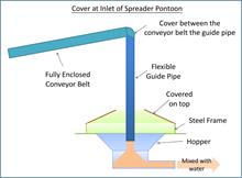
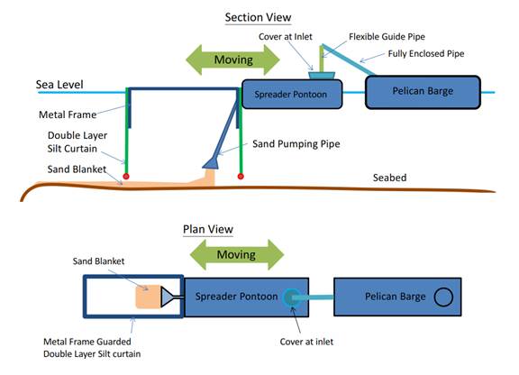
Spreader Pontoon for Sand Blanket Laying
|
Figure B.2: Illustrations of Silt Curtain Arrangement surrounding Spreader Pontoon |
|
|
|
|
|
|
|
B.3
Closed Grab Methods for Sand Blanket Laying, Marine Filling and Field Joint Excavation (for the submarine cable
diversion)
|
Figure B.3: Illustrations of Silt Curtain Arrangement surrounding Close Grabs |
|||
|
|
|
||
|
|||

B.4
Customised Design for Sand Blanket Laying - Combined Metal
Plated + Fabric Silt Curtain
|
Figure B.4: Illustration of Combined Metal Plated + Fabric Silt Curtain Arrangement surrounding the Grabs |
|
|

B.5
Customised Design for Sand Blanket Laying - Adjustable
Rectangular Chute and Movable Box Silt Curtain
Figure B.5: Illustration of Cage-Type Silt Curtain comprising Rectangular Chute and Movable Box

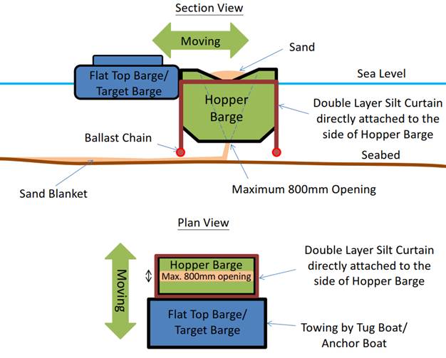
B.6
Customised Design for Sand Blanket Laying – Hopper Barge
with Silt Curtain Enclosure
|
Figure B.6: Illustration of Silt Curtain surrounding the Hopper Barge |
|
|
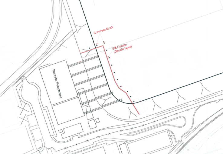
B.7
Modification of Existing Seawall
|
Figure B.7: Tentative Layout of Silt Curtains for Modification at the Submarine Cable Landing Point |
|
|

B.8
Piling Activities (for construction of new runway approach
lights and HKIAAA marker beacons)
B.9
WSR C7a
Appendix
C.
Implementation Schedule of
Enhanced Silt Curtain for Marine Filling Works
|
|
Implementation Schedule of Enhanced Silt Curtain for Marine Filling Works |
||
|
Conditions |
Implemented by |
Checked by |
|
At the commencement of marine filling activities · The indicative enhanced silt curtain arrangement presented in Figure B.1(a) of Silt Curtain Deployment Plan (SCDP) shall be followed; and |
Contractor |
ET & IEC |
|
· An advance seawall of at least 200m shall be provided in accordance with Condition 2.26 (ii) of Environmental Permit. |
|
|
|
Throughout the construction period of marine filling activities · If there are any changes on the arrangement of enhanced silt curtain system as shown in Figure B.1(a), the Contractor is required to submit updated silt curtain plans for agreement with AAHK, ET and IEC. |
Contractor
|
AAHK, ET & IEC |
|
Maintenance of enhanced silt curtain · The Contractor shall inspect the enhanced silt curtains regularly and carry out necessary maintenance taking into account the site conditions, with details to be agreed with ET. |
Contractor |
ET & IEC |
|
Phasing out of enhanced silt curtain · When seawalls are completed for a certain section, enhanced silt curtain will be phase out. The Contractor shall maintain an overlapping length of at least 150m for seawall and enhanced silt curtain. |
Contractor |
ET & IEC |
|
Arrangements of the Enhanced Silt Curtain (As shown in Figure B1(a) of SCDP) |
||||
|
Case |
Arrangement |
Implemented by |
Checked by |
|
|
A |
Eastern side of the project area |
· No marine filling activities (except filling activities for construction of seawall) shall be undertaken within the no marine filling zone as indicated in Figure B.1(a) of SCDP for Case A if there is no seawall to the immediate west of the opening; or · An interim silt curtain should be added to the north of inner enhanced silt curtain if marine filling activities are undertaken within no marine filling zone before seawall construction. |
Contractor |
ET & IEC |
|
B |
Northern side of the project area |
· No marine filling activities (except filling activities for construction of seawall) shall be undertaken within the no marine filling zone as indicated in Figure B.1(a) of SCDP for Case B if there is no seawall to the immediate south of the opening. |
Contractor |
ET & IEC |
|
C |
Western side of the project area |
· No marine filling activities (except filling activities for construction of seawall) shall be undertaken within the no marine filling zone as indicated in Figure B.1(a) of SCDP for Case C if there is no seawall to the immediate east of the opening; or · An interim silt curtain should be added to the west of the future runway if marine filling activities are undertaken within no marine filling zone before seawall construction. |
Contractor |
ET & IEC |
|
D |
Southwestern side of the project area |
· No marine filling activities (except filling activities for construction of seawall) shall be undertaken within the no marine filling zone as shown in Figure B.1(a) of SCDP for Case D if there is no seawall to the immediate east of the openings. |
Contractor |
ET & IEC |
|
Southwestern side of the project area (later stage) |
· A localised silt curtain shall be provided to the west of the existing north runway if marine filling activities are undertaken to the west of the existing north runway when there is a temporary opening at the seawall (see Case D as shown in Figure B.1(a) of SCDP). |
Contractor |
ET & IEC |
|
Appendix
D.
Example Silt Curtain
Inspection Checklists
|
|
Daily Visual Inspection Checklist for Silt Curtains |
||||||
|
Contract No.:__________________ Date:________________________ Weather:_____________________ |
||||||
|
Inspection Items |
Result |
If Unsatisfactory, provide details on the following |
||||
|
Affected Section(s) / Location(s) |
Description of Unsatisfactory Item |
Proposed Action |
Date of Completion of Action |
Confirmed / Completed By (name and signature) |
||
|
Geotextile |
||||||
|
Curtain remains intact and without gap |
□Satisfactory □Unsatisfactory |
|
|
|
|
|
|
Curtain in upright position |
□Satisfactory □Unsatisfactory |
|
|
|
|
|
|
Curtain has no loose / flapping parts |
□Satisfactory □Unsatisfactory |
|
|
|
|
|
|
No floating refuse trapped by the silt curtain |
□Satisfactory □Unsatisfactory |
|
|
|
|
|
|
No sediment plume through the silt curtain observed |
□Satisfactory □Unsatisfactory |
|
|
|
|
|
|
Ancillary Components |
||||||
|
Floaters are intact and not submerged |
□Satisfactory □Unsatisfactory |
|
|
|
|
|
|
Marker buoys and flashing lights are in correct positions and undamaged |
□Satisfactory □Unsatisfactory |
|
|
|
|
|
|
Flashing lights are working properly |
□Satisfactory □Unsatisfactory |
|
|
|
|
|
|
No parts are detached from the silt curtain system |
□Satisfactory □Unsatisfactory |
|
|
|
|
|
Checked By:_________________________
|
Diver Inspection Checklist for Silt Curtains |
||||||
|
Contract No.:__________________ Date:________________________ Weather:_____________________ |
||||||
|
Inspection Items |
Result |
If Unsatisfactory, provide details on the following |
||||
|
Coordinate / Locations of Affected Section(s) |
Description of Unsatisfactory Item |
Proposed Action |
Date of Completion of Action |
Confirmed / Completed By (name and signature) |
||
|
Geotextile |
||||||
|
Curtain remains intact and without gap |
□Satisfactory □Unsatisfactory |
|
|
|
|
|
|
Curtain in upright position |
□Satisfactory □Unsatisfactory |
|
|
|
|
|
|
Curtain has no loose / flapping parts |
□Satisfactory □Unsatisfactory |
|
|
|
|
|
|
Curtain is securely attached at joints |
□Satisfactory □Unsatisfactory |
|
|
|
|
|
|
Curtain fittings (e.g. chains, bands, plates, joint connectors etc.) are intact and in position |
□Satisfactory □Unsatisfactory |
|
|
|
|
|
|
Curtain extends to within 30cm from seabed level (for floating type) |
□Satisfactory □Unsatisfactory |
|
|
|
|
|
|
Curtain hem is not weighted down by sediment deposition |
□Satisfactory □Unsatisfactory |
|
|
|
|
|
|
Ancillary Components |
||||||
|
Anchors are undamaged and positions are correct |
□Satisfactory □Unsatisfactory |
|
|
|
|
|
|
Anchor lines are properly attached to the buoys / connectors of the silt curtain |
□Satisfactory □Unsatisfactory |
|
|
|
|
|
|
No parts are detached from the silt curtain system |
□Satisfactory □Unsatisfactory |
|
|
|
|
|
Checked By:_________________________